

How to Use a Wire Tracer Safely
A practical homeowner guide to identifying cables, following hidden routes, and avoiding the dangerous mistake of connecting the wrong tracer to an energized circuit.
Affiliate disclosure: Accurate Goods may earn a commission from qualifying Amazon purchases made through links on this page, at no extra cost to you. Tool recommendations are based on documented use cases, safety limits, and homeowner usefulness—not unverified testing claims.
Quick Answer
To use a wire tracer safely, first identify whether you are working on household electrical wiring or a disconnected low-voltage cable. Verify the circuit state with appropriate test equipment, connect the transmitter exactly as the tracer manual requires, begin scanning with the receiver at higher sensitivity, and gradually reduce sensitivity as you approach the target. Never connect an ordinary network toner to energized mains wiring. A tone is evidence of a likely path—not permission to drill, cut, or touch a conductor.
Compare Wire Tracer Kits →
Wire Tracer Safety Starts With the Tool Type
The term “wire tracer” covers tools that may look similar but are designed for very different electrical environments. A household circuit tracer may support energized branch circuits when connected according to the manufacturer’s procedure. A network toner normally sends a low-energy tone through disconnected Ethernet, telephone, coax, speaker, alarm, thermostat, or other low-voltage cable. Interchanging those tools can damage equipment or expose the user to shock, fire, and arc hazards.
| Tracer type | Typical use | Usual cable state | Main caution |
|---|---|---|---|
| Electrical circuit tracer | Branch circuits, breakers, hidden power wiring | Model-dependent | Use only within documented voltage/category ratings |
| Breaker finder | Match an outlet to a panel breaker | Usually energized outlet | Does not always trace the full cable route |
| Analog tone and probe | Phone, speaker, coax, inactive data cable | Normally disconnected | Never assume it is safe on mains voltage |
| Digital network toner | Identify compatible active or inactive network links | Model-dependent | It is not an electrical branch-circuit tracer |
Non-negotiable rule: The exact model manual—not the product name, package color, or seller description—determines which voltage, wiring category, and connection method are allowed.
Identify the Cable and Define the Job
Start by writing down what you are trying to learn. Are you matching an outlet to a breaker, following a cable behind drywall, locating the far end of an Ethernet run, identifying a speaker wire in a bundle, or checking which coax reaches a room? This prevents a common mistake: selecting a tool because it is marketed as a wire tracer even though it does not answer the specific question.
Inspect both likely ends of the cable. Look for outlet shape, jacket markings, connector type, nearby equipment, panel labels, and where the cable enters the wall. Do not infer that a thin cable is automatically low voltage. Old alarm, doorbell, telephone, and thermostat wiring can be repurposed or connected in unexpected ways. A previous owner may also have left disconnected cable beside energized conductors.
- Photograph the starting condition
- Note every connected device
- Map likely cable destinations
- Choose the tracer for that cable type
- Unknown exposed conductors
- Heat, scorch marks, or damaged insulation
- Water near wiring
- Unclear service-panel work
Read the Manual and Inspect the Tracer
Find the instructions for the exact model number printed on the transmitter and receiver. Check the maximum voltage, measurement category, whether the tool allows energized tracing, approved accessories, grounding method, connection diagrams, and warning symbols. Some kits include multiple leads, but an included connector does not make every possible connection safe.
Inspect the housing, battery compartment, leads, clips, plug adapters, and probe tip. Replace leaking batteries and damaged accessories. Do not tape over cracked insulation or improvise an adapter. Turn the transmitter and receiver on away from the target cable first so you understand the indicators, sensitivity control, battery status, and sound pattern.
Check Klein ET450 Availability →
Verify Whether the Circuit Is Energized
Do not rely only on a switch position, breaker label, disconnected appliance, or another person’s statement. Use an appropriate tester and the correct test method for the environment. A non-contact voltage detector is useful for preliminary screening, but it can produce false positive or false negative indications because of distance, shielding, induced voltage, batteries, and sensitivity. When de-energization matters, confirm with a properly rated contact tester and prove that tester on a known source before and after the check.
If you are working on low-voltage communications cable, disconnect it from routers, switches, televisions, amplifiers, telephone interfaces, powered injectors, and other equipment unless the tracer manual specifically supports that connection. Power over Ethernet can place voltage on network pairs even when a cable appears to be “just data.” Coax may be connected to powered distribution equipment. Alarm and thermostat circuits can also carry voltage.
When the cable state cannot be established confidently, stop. The correct response to uncertainty is not to attach the transmitter and see what happens. Ask a qualified electrician or low-voltage technician to identify and isolate the circuit.
Connect the Transmitter Correctly
Follow the diagram in the manual. On a compatible outlet-based breaker finder, the transmitter may plug directly into a receptacle. On an advanced circuit tracer, the manufacturer may specify a grounded outlet connection, separate leads, or a particular reference ground. On a disconnected low-voltage cable, a toner might connect through RJ45, RJ11, coax, or insulated clips. The correct arrangement helps keep the user safe and improves signal quality.
A poor reference connection can make the trace weak or cause the signal to couple into multiple nearby conductors. Do not connect a clip to an unknown metal surface simply because it appears grounded. Do not allow clips to touch each other, exposed conductors, or grounded metal. Keep fingers behind protective guards and make connections with the circuit in the state required by the manual.
Confirm that the transmitter is actually sending
Check the transmitter’s status indicator, mode, and battery condition. If the receiver can detect the tone close to the transmitter, perform that check before scanning a wall or cable bundle. This simple test prevents spending twenty minutes following a nonexistent signal caused by a dead battery, loose plug, wrong mode, or open connection.
Scan Broadly, Then Reduce Sensitivity
Begin near the known cable end. Hold the receiver in the orientation recommended by its manual and move slowly. Start with enough sensitivity to confirm the general direction, then lower sensitivity in small steps as the signal becomes stronger. Maximum sensitivity is useful for discovery, but it often makes a large section of wall or an entire bundle appear active.
Follow a grid rather than waving the probe randomly. Scan horizontally and vertically, mark only repeatable signal peaks, and approach the route from both sides. Around a panel or dense bundle, compare neighboring conductors before deciding which one is the target. Keep the receiver away from the transmitter leads when possible because those leads may radiate a stronger signal than the hidden cable.
- Move slowly at a consistent distance
- Repeat each signal from another direction
- Lower sensitivity near the target
- Mark a broad estimated route
- Scanning only at maximum sensitivity
- Following the loudest point once
- Assuming signal strength equals depth
- Ignoring adjacent parallel conductors
View Fluke Pro3000F60 Kit →
Confirm the Far End Before Labeling
Finding a strong tone at one cable is not enough when several cables share a route. Disconnect and reconnect the transmitter when safe, change the tone pattern if supported, and verify that the signal disappears and returns at the suspected far end. For paired communication cable, a compatible pair-identification feature may help separate conductors. For a branch circuit, compare the tracer result with the expected outlets, switches, breaker position, and wiring path.
After confirmation, label both ends with a durable identifier that describes destination rather than a temporary device. Update a simple cable map or panel schedule. Good labeling turns one successful tracing session into a permanent improvement and reduces risky guesswork during the next repair.
How to Trace Common Cable Types
Ethernet cable
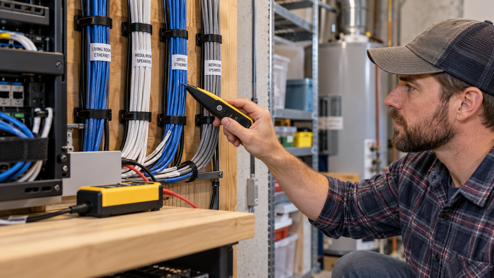
Disconnect the target cable from network equipment unless the tracer explicitly supports active links. Confirm that Power over Ethernet is absent. Connect the compatible RJ45 transmitter, choose a tone, and scan the remote patch area with the probe. A toner identifies the cable; it does not certify speed, category performance, wire map, or signal quality. Use a cable tester or certifier for those questions.
Coax cable
Disconnect the coax from powered equipment and distribution amplifiers. Use a compatible F-connector adapter or the method specified by the kit. Shielding may change the signal response, so check the far-end connector directly and compare all candidate cables. Avoid bending coax sharply or loosening connectors by twisting the cable.
Speaker, alarm, doorbell, and thermostat wire
Isolate the cable from amplifiers, transformers, alarm panels, and HVAC controls before applying a tone. Verify that no voltage is present. Clip to the conductors only as documented, separate candidate pairs, and confirm the far end by changing or removing the tone. Do not short conductors together to “make the signal stronger.”
Household branch wiring
Use only a tracer specifically rated for the circuit state and voltage. Connection, grounding, receiver orientation, and panel scanning are model-specific. If the procedure requires removing a panel cover, contacting exposed conductors, or working near service equipment, hire a qualified electrician. Homeowner ownership of a professional tool does not substitute for training.
View Sperry ET64220 →
Why a Wire Tracer Gives False or Wide Signals
Signal coupling is the most common source of confusion. Parallel conductors can pick up part of the transmitted signal, especially when they share a grounded system, conduit, shield, cable tray, or long route. Metal studs, foil insulation, pipes, damp materials, and reinforced walls may weaken or redirect the response. A transmitter connected without the recommended reference can also spread the signal widely.
First verify the transmitter close to the source. Then lower receiver sensitivity, scan from both sides, move away from the transmitter leads, and compare repeatable peaks. If safe and allowed, isolate competing branches or disconnect remote equipment. Never defeat a grounding conductor or open an energized enclosure merely to improve tracing performance.
Depth estimates are also unreliable. Signal strength depends on more than distance, so a strong signal does not prove that a cable is close to the surface. Treat the traced line as a corridor, not an exact centerline. Before drilling or cutting, inspect both sides of the wall, consider outlet and switch positions, use an appropriate wall scanner, and choose the least invasive method.
Tools That Complement a Wire Tracer
A tracer identifies or follows a signal, but it does not answer every safety question. A properly rated non-contact voltage tester can help with preliminary screening. A multimeter or two-pole tester can provide contact voltage checks when used by someone who understands the method. A receptacle tester checks certain outlet wiring conditions, while a network cable tester evaluates pair continuity and wire map.
For choosing the correct tracer, compare our best wire tracers for home use. If your only goal is matching receptacles to breakers, see the best circuit breaker finders. Before beginning electrical troubleshooting, review how to check if a wire is live.
Frequently Asked Questions
Can I use a wire tracer on a live circuit?
Only when the exact tracer model and connection method are explicitly rated for that energized circuit. Ordinary network tone generators should not be connected to household mains wiring.
Can a wire tracer show the exact place to drill?
No. A tracer indicates a likely signal path, and the signal can couple into nearby conductors or metal. Use additional inspection methods and maintain a safe margin before drilling.
Why can I hear the tone on several wires?
High sensitivity, parallel runs, shared grounding, shielding, bundles, or remote connected equipment can spread the signal. Lower sensitivity and verify by disconnecting and reconnecting the transmitter when safe.
Can I trace Ethernet while it is connected to a router?
Only if the tracer manual supports that configuration. Otherwise disconnect the cable and confirm that Power over Ethernet is absent before attaching the transmitter.
Is a breaker finder the same as a wire tracer?
No. A breaker finder mainly identifies which breaker supplies an outlet. A wire tracer may follow a route or distinguish one conductor among many, although advanced electrical kits may do both.
When should I call an electrician?
Call one when circuit state is uncertain, wiring is damaged or wet, overheating is present, the work involves service equipment or exposed energized parts, or the required procedure is beyond your training.
Final Safety Checklist
Identify the cable, select the correct tracer, read the exact manual, inspect the leads, verify the circuit state, disconnect incompatible equipment, connect the transmitter exactly as documented, scan broadly, reduce sensitivity, confirm from both ends, and label the result. Stop whenever the wiring condition or voltage cannot be established confidently.
Compare Wire Tracers on Amazon →
